How to Choose the Best Heat Resistant Coil?
Choosing a Heat Resistant Coil begins with a clear view of its real operating conditions. Record the working temperature, heating cycles, electrical load, surrounding atmosphere, and available space. A coil facing steady heat may behave differently from one repeatedly heated and cooled. Small details matter. A tight bend or poor airflow can create a local hot spot, even when the average temperature seems acceptable.
The U.S. Department of Energy’s 2022 Industrial Decarbonization Roadmap describes industry as a major energy user and emissions source. That context makes efficient, durable process heating an important engineering concern. It does not identify one coil material as best. Selection still depends on the application. Alloy composition, wire diameter, coil geometry, surface loading, and mounting method all affect performance. Manufacturer temperature ratings also need careful reading; maximum ratings are not always suitable continuous operating targets.
This guide explains how to compare those factors and ask suppliers for useful evidence. Request data for the actual alloy and coil design, including operating limits, resistance, and expected service conditions. Check whether the test setup resembles your equipment, not just a laboratory fixture. A datasheet can help, but it cannot capture every installation. That is worth remembering. If the atmosphere, duty cycle, or cooling pattern is uncertain, treat the first specification as provisional and validate it against measured operating data. The best Heat Resistant Coil is the one that meets the thermal and electrical demands reliably, with a sensible margin—not simply the one with the highest advertised temperature.
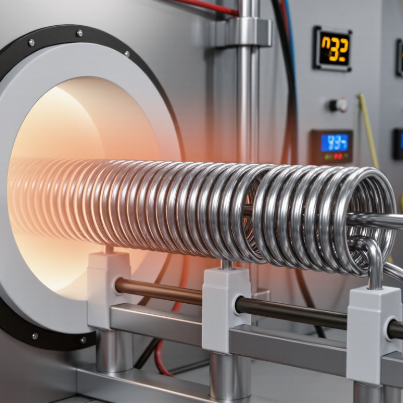
What Is a Heat-Resistant Coil and Where Is It Used?
A heat-resistant coil is a winding of insulated wire designed to operate at elevated temperatures without rapid insulation breakdown or loss of electrical performance. It may sit around a magnetic core, or be shaped to create a magnetic field in a motor, transformer, or solenoid. The coil itself is only part of the system. Its insulation, core, terminals, and surrounding materials also affect heat tolerance. Small details matter.
These coils are used in industrial motors near hot machinery, transformers in warm enclosures, heating equipment, and vehicle components exposed to engine heat. In a motor, for example, repeated starts can warm the windings even when the surrounding room feels cool. Some applications face brief temperature spikes; others run hot for hours. Those conditions call for different designs.
When assessing a coil, check its rated temperature alongside ambient heat, duty cycle, airflow, vibration, and nearby moisture. A rating alone can mislead: internal hot spots may exceed the temperature measured outside the housing. In practice, a terminal with poor contact or cramped wiring can create extra heat. The specification may look complete, yet still overlook the installation. Engineers should compare the coil’s insulation system and expected service conditions, not just its maximum temperature figure.
How to Choose the Best Heat-Resistant Coil?
Compare typical maximum element temperatures for common resistance-alloy families. Choose a coil based on its operating temperature, atmosphere, service life, and electrical requirements.
Temperatures shown are approximate maximum element temperatures in air; actual limits depend on alloy grade, wire diameter, coil design, and operating conditions.
Which Operating Conditions Should You Define First?
Before choosing a heat-resistant coil, define the actual temperature profile, not just the furnace setpoint. Record normal temperature, brief peaks, ramp rate, and time at temperature. A coil exposed to 1,000°C for minutes may behave differently from one held there all shift. Include start-up and shutdown cycles; repeated expansion can matter as much as peak heat. Small details count.
Next, describe the environment around the coil. Is it air, vacuum, or process gas? Note humidity, dust, chemical vapors, scale, and contact with workpieces. Specify electrical conditions too: supply voltage, power range, control method, and cycling frequency. Include mounting space, coil diameter, wire supports, and airflow. A drawing and operating logs are better than a guessed temperature. A neat spreadsheet can still hide a poorly placed sensor. Check the measurement location.
Tips: Share average and worst-case conditions with the supplier or engineer. Ask what test data supports the recommended material and expected service life. Leave room for uncertainty; old readings may come from a different location. Keep a failed coil sample, if available, and record where it broke. That evidence may help distinguish oxidation, overheating, or mechanical strain.
How Do Coil Materials Compare at High Temperatures?
Coil materials behave differently once heat, air, and electrical load act together. The Nickel Institute’s High-Temperature Characteristics of Stainless Steels lists about 1,050°C as a continuous-use limit for type 310 stainless steel in oxidizing conditions. Treat that as an oxidation guideline, not a safe coil operating temperature. Wire diameter, supports, airflow, and cycling can lower the practical limit. Small details matter.
Nickel-chromium alloys generally resist oxidation and repeated heating better than ordinary stainless steels, but they cost more and may still creep under prolonged load. Iron-chromium-aluminum alloys form a protective alumina layer; technical data commonly place some element grades near 1,400°C maximum element temperature. That figure is not a blanket rating for a finished coil. ASM Handbook high-temperature materials data also show why atmosphere matters: sulfur-bearing or reducing gases can undermine protection that works in clean air. A furnace with visible scale or uneven heating is already telling you something. I would compare the supplier’s continuous-use rating, not just its peak number, then check it against the actual atmosphere and duty cycle. Even that leaves uncertainty: real coil life depends on installation and repeated thermal shock.
What Design and Compatibility Factors Affect Coil Performance?
A heat-resistant coil must match the real operating temperature, not just a number on a datasheet. Check the alloy, wire diameter, and winding spacing together. Thicker wire may tolerate more current, but it can also heat more slowly.
Tight turns can create local hot spots when airflow is limited. Small gaps matter.
Compatibility is just as important. Confirm the coil’s resistance suits the power supply, then check connector size, mounting space, and insulation ratings. A coil that fits electrically may still rub against a housing or lose heat unevenly.
Thermal expansion can loosen a mount after repeated heating and cooling. This is easy to overlook. In practice, test the assembly under its expected load and watch temperature at several points, not only near the center.
Record the warm-up time and inspect connections for discoloration. A neat calculation can still miss an uneven airflow path or a poorly seated terminal. I would not treat one successful run as proof; repeat the test after cooling, because performance can shift slightly between cycles.
How Can You Verify Quality, Safety, and Service Life?
A heat-resistant coil should be verified by test evidence, not a temperature claim alone. Ask for the alloy grade, wire diameter, resistance tolerance, and a material certificate tied to the production batch. Then compare measured cold resistance with the drawing and repeat the measurement after a controlled heating cycle. Small deviations matter. They can signal uneven winding, poor joints, or incorrect wire size. IEC 60216 defines thermal endurance testing for electrical insulating materials; its temperature index is linked to an estimated 20,000-hour endpoint. That is a test basis, not a promise that a finished coil will last 20,000 hours.
Safety checks should match the coil’s actual assembly and operating conditions. For insulated electrical systems, IEC 60085 lists thermal classes including 155°C and 180°C; these ratings apply to insulation systems, not automatically to the heating wire. Request insulation-resistance and dielectric-withstand results where relevant, plus a temperature map taken at rated voltage, load, and airflow. Check for hot spots near terminals and bends. A perfect-looking report can still miss a loose connection. I would question any test that omits the test temperature, instrument details, or sample identification. Service life also depends on switching frequency, contamination, vibration, and installation. Record these conditions during validation, then inspect resistance and physical damage at planned intervals.
