What Are Quick Connect Couplers and How Do They Work?

Quick Connect Couplers appear in many hydraulic, pneumatic, and fluid-transfer systems. They connect hoses, tools, and equipment without requiring a wrench every time. A mechanic may hear a sharp click as the sleeve locks. Inside, valves open and allow fluid or air to pass through the coupling. When disconnected, those valves close and help limit leakage, contamination, and pressure loss.

Paul J. Michael, a respected fluid-power educator and engineer, captures the practical priority clearly: “Reliable connections begin with cleanliness, correct sizing, and controlled pressure.” That principle matters in workshops, factories, agricultural equipment, and mobile machinery. A coupler can look secure while remaining partially engaged. That small mistake may cause heat, leakage, or unexpected equipment movement. It deserves attention.

This guide explains how Quick Connect Couplers work, including their locking mechanisms, internal valves, pressure ratings, and material choices. It also examines different coupling styles, such as ball-lock, flat-face, screw-to-connect, and pneumatic designs. Each type serves a different operating environment. Some tolerate frequent connection cycles. Others protect sensitive hydraulic circuits from excessive fluid loss.

Real-world selection is rarely perfect. A compact coupler may improve access but restrict flow. A high-flow model may add weight or cost. Even experienced technicians can overlook trapped pressure. Therefore, proper installation, inspection, and maintenance remain essential. Clean ports, compatible seals, and verified ratings create safer, more dependable connections. The details are small. The consequences are not.
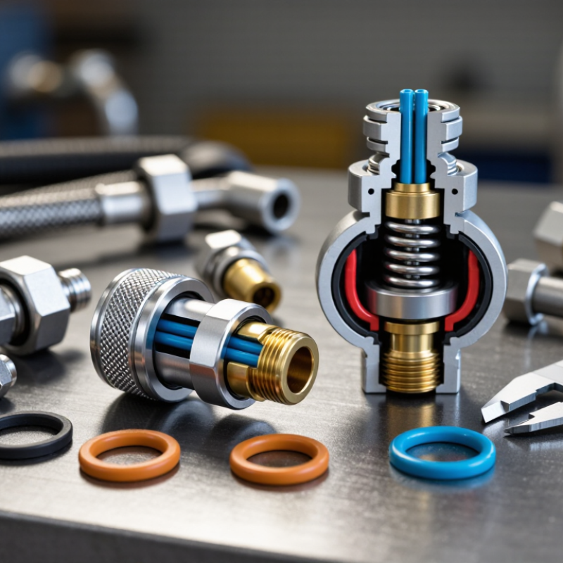
What Are Quick Connect Couplers and How Do They Work?

Quick Connect Coupler Definition and ISO 7241 Classification

Quick connect couplers are removable hydraulic fittings that join hoses, tubes, or equipment without lengthy wrench work. Their internal valves open when the halves connect and close when separated. This limits fluid loss and reduces air entry. However, connection should never be forced under trapped pressure. That small mistake can damage seals or cause sudden movement.

ISO 7241 is central to coupler classification. It defines two main families: Series A and Series B. Both use standardized dimensions and performance requirements, but their interchangeability patterns differ. Series A is widely selected for general hydraulic applications, while Series B is common in many industrial and mobile systems. A Series A half should not be assumed compatible with a Series B half. That detail matters. The standard does not automatically confirm pressure, temperature, fluid, or flow suitability.

During selection, technicians should verify the series, nominal size, connection type, working pressure, and material compatibility. A clean-looking coupler can still contain worn valves or damaged O-rings. Inspect the mating surfaces before connection. Push the halves fully together, then check the locking sleeve and test for leakage at low pressure. Dust caps help, but they are not perfect. In real maintenance work, contamination and side loading often cause more trouble than the coupling design itself. ISO classification provides a reliable starting point, yet field conditions still require careful judgment.

Core Components: Valves, Balls, Sleeves, Seals, and Locking Systems

Quick connect couplers join fluid lines without prolonged threading or specialized tools. Their compact bodies hide several carefully matched parts. A technician pushes the male plug into the female socket, and internal valves open to create a continuous passage. When disconnected, the valves close quickly, limiting fluid loss and reducing air entry.

The valves control flow on both sides of the connection. Some designs use poppet valves, while others use ball-based sealing elements. Locking balls sit inside the sleeve and grip a groove on the plug. Sliding the sleeve backward releases them; moving it forward secures the joint. The sleeve must move smoothly. A gritty sleeve often signals contamination, worn surfaces, or insufficient cleaning.

Seals, commonly shaped as O-rings, prevent leakage around moving and stationary parts. They need compatible materials, correct sizing, and light lubrication when specified by the manufacturer. A damaged seal may leak only under heat or pressure, making diagnosis less obvious. I have found that operators often inspect the valve first and overlook the seal groove. That habit deserves reconsideration. Before service, check pressure ratings, clean both halves, and inspect for scratches, corrosion, or trapped debris. Never assume a connection is secure because it clicks. A gentle pull test and a slow pressure check can reveal a poor lock.

What Are Quick Connect Couplers and How Do They Work? - Core Components: Valves, Balls, Sleeves, Seals, and Locking Systems

Core Component Primary Function How It Works in a Coupler Common Materials Typical Failure Mode Recommended Inspection
Body Provides the pressure boundary and houses the internal components. The body contains the fluid passage, valve seat, sleeve, locking mechanism, and seal grooves. Plated carbon steel, stainless steel, brass, or engineered thermoplastics. Corrosion, thread damage, cracking, or deformation from excessive pressure or impact. Check for corrosion, dents, damaged threads, and visible leakage around joints.
Valves Control fluid flow and reduce spillage during disconnection. A valve in each mating half opens when the coupler halves are connected and closes when they are separated. This creates a shut-off function in both halves. Hardened steel, stainless steel, brass, or polymer valve components. Valve sticking, incomplete opening, contamination, or leakage after disconnection. Connect and disconnect at zero or controlled pressure; check for smooth movement and shut-off leakage.
Balls Retain the sleeve or locking ring and hold the mating plug in position. Multiple hardened balls move into a circumferential groove on the plug. The sleeve prevents the balls from moving outward while the coupler is locked. Hardened carbon steel, stainless steel, or corrosion-resistant alloy steel. Pitting, flattening, corrosion, loss of balls, or incomplete engagement in the plug groove. Inspect the ball track and plug groove; verify that all balls move freely and engage evenly.
Sleeve Controls locking and unlocking of the coupler halves. Pulling the sleeve back releases the balls for connection or disconnection. Releasing the sleeve allows it to return and cover the balls. Plated steel, stainless steel, aluminum, or reinforced polymer. Jamming, bent sleeve, damaged spring, or failure to return to the locked position. Slide the sleeve through its full travel and confirm automatic return and positive locking.
Seals Prevent fluid leakage between internal parts and at the mating interface. O-rings, backup rings, and face seals are compressed against machined surfaces to maintain a fluid-tight connection. Nitrile rubber, fluorocarbon rubber, ethylene propylene rubber, polyurethane, or polytetrafluoroethylene. Hardening, swelling, cuts, extrusion, chemical attack, or leakage caused by incorrect temperature or fluid compatibility. Inspect for cuts, flattening, discoloration, and swelling; replace seals during scheduled service.
Locking System Prevents accidental separation under vibration, tension, or pressure. The locking sleeve, balls, retaining ring, and sometimes a secondary safety device work together to secure the plug in the socket. Hardened steel, stainless steel, springs, retaining rings, and elastomeric parts. Incomplete locking, worn grooves, damaged retaining components, or accidental sleeve movement. Perform a manual pull-check after connection and verify that the sleeve is fully forward and secured.
Plug Provides the mating profile that enters the socket and forms the flow connection. The plug pushes the valves open and presents a groove or shoulder for the locking balls to engage. Hardened steel, stainless steel, brass, or compatible engineering plastic. Scratched sealing surfaces, worn locking groove, incorrect profile, or contamination. Clean before connection and inspect the nose, sealing surface, and locking groove for damage.
Spring and Retainer Returns moving parts to their normal position and keeps internal components in place. The spring biases the sleeve or valve toward its resting position, while retainers prevent internal parts from escaping. Stainless steel, spring steel, carbon steel, or corrosion-resistant alloys. Spring fatigue, corrosion, breakage, or displaced retaining ring. Check return force, corrosion, retaining-ring position, and abnormal looseness during service.

Typical Operating and Selection Data

Data Dimension Representative Range or Requirement Why It Matters
Connection Method Manual sleeve operation; some designs include a secondary locking feature. Enables faster connection than threaded fittings while maintaining mechanical retention.
Nominal Port Sizes Common hydraulic sizes range from approximately 1/8 inch to 2 inches; pneumatic sizes are often smaller. Port size affects flow capacity, pressure drop, hose compatibility, and overall coupling dimensions.
Pressure Rating Application-specific; hydraulic couplers may be rated from several dozen bar to several hundred bar, while pneumatic couplers are commonly rated lower. The allowable working pressure depends on size, material, valve design, temperature, and the applicable standard. The manufacturer’s rating must be followed.
Temperature Range Typically about −40°C to +120°C for many general-purpose elastomer-sealed designs; specialized seal materials can extend the range. Temperature changes affect seal hardness, swelling, pressure capability, and service life.
Flow Direction One-way or bi-directional, depending on valve configuration. Valve geometry can create pressure drop and may limit flow direction or allowable back pressure.
Pressure During Connection Connection and disconnection should normally occur with the circuit depressurized unless the coupler is specifically designed for connection under pressure. Trapped pressure can prevent valve movement, increase connection force, and create a safety hazard.
Fluid Compatibility Must be confirmed for the fluid, concentration, temperature, pressure, and seal material. Incompatible fluids can cause seal swelling, cracking, corrosion, or loss of mechanical strength.
Maintenance Interval Inspect before use; clean mating surfaces routinely; replace damaged seals and worn parts as needed. Regular inspection limits contamination-related wear, leakage, accidental release, and unplanned downtime.

How Couplers Connect, Seal, Pressurize, and Disconnect Step by Step

What Are Quick Connect Couplers and How Do They Work?

Quick connect couplers join fluid lines without tools. A typical assembly has a plug, socket, locking sleeve, valve, and seal. During connection, the plug enters the socket and pushes the internal valve open. Locking balls or a sleeve then hold both halves together. The seal compresses around the plug, creating a leak-resistant path.

Pressurization should happen only after full engagement. Air, water, or hydraulic fluid then travels through the aligned passage. A small gap, damaged O-ring, or mismatched profile can cause leakage under pressure. The U.S. Department of Energy’s Improving Compressed Air System Performance guide estimates that leaks and related losses can waste 20–30% of compressed-air capacity. That makes sealing a performance issue, not merely a cleanliness concern. ISO 4414 also emphasizes safe pneumatic system design and controlled energy release. I sometimes underestimate the locking check. A click is not proof of a secure connection.

Tips: Match pressure, temperature, fluid, and flow ratings before installation. Wipe the plug clean, inspect the O-ring, and pull the sleeve lightly after coupling. To disconnect, isolate the supply, release trapped pressure, and hold the hose firmly. Pulling against pressure is unsafe and can damage the valve. Some couplers disconnect easily, but others need a deliberate sleeve movement. Never force them. Follow the manufacturer’s coupling profile and applicable ISO guidance, because similar-looking parts may not seal correctly.

Performance Data: Rated Pressure, Flow Capacity, Leakage, and Cycle Life

What Are Quick Connect Couplers and How Do They Work?

Quick connect couplers join fluid lines without using tools. Their performance depends on pressure, flow, sealing, and repeated cycling. Hydraulic models commonly carry rated pressures from 100 to 420 bar, while pneumatic versions often operate near 8–10 bar. These figures are design limits, not permanent operating targets. ISO 7241:2010 requires dimensional and performance consistency, but actual ratings still depend on materials, temperature, and connection size.

Flow capacity must be checked with pressure-drop data. A small hydraulic coupler may handle roughly 10–20 L/min, while larger bodies can exceed 100 L/min. At rated flow, many ISO-tested assemblies show pressure losses around 0.2–1 bar. That loss creates heat. It also reduces actuator speed. One detail is easy to miss: a larger port does not always mean higher flow. Internal poppets can become the restriction.

Leakage deserves separate measurement. ISO 18869:2017 provides test methods for leakage, impulse pressure, and endurance, but it does not impose one universal cycle-life number. Industry test sheets commonly report leakage below 0.01–0.1 mL per connection, although contamination can change results quickly. Ten thousand cycles is a frequent endurance target; heavy-duty designs may exceed 100,000 cycles. I would treat those figures cautiously. Misalignment, side loading, and trapped pressure often shorten real service life more than the laboratory test suggests.

Safety, Material Selection, and ISO 16028 Flush-Face Applications

Quick connect couplers join hydraulic lines without tools, reducing service time around machinery. The male and female halves align, then a sleeve locks them together. Internal poppets open only after proper engagement. Disconnection reverses this action and limits fluid release. Not perfectly, though. Trapped pressure, dirt, or side loading can prevent full connection.

Safety depends on more than working pressure. The U.S. Bureau of Labor Statistics recorded about 2.6 million nonfatal workplace injuries in private industry during 2023. Couplers are not responsible for all incidents, but poor hose handling can increase exposure to injection injuries and sudden movement. Depressurize both lines, inspect the locking sleeve, and never connect by force. A small leak can look harmless. It is not.

ISO 16028 flush-face couplers use flat mating surfaces, limiting air entry and fluid loss during connection. This design suits mobile equipment, test rigs, and environments where contamination damages valves. Carbon steel offers strength and cost efficiency; stainless steel performs better against corrosion. Seal selection matters just as much. Nitrile suits many mineral oils, while fluorocarbon compounds tolerate higher temperatures and aggressive fluids. Always compare chemical compatibility, temperature, flow, and pressure ratings with the actual fluid. ISO 16028 defines interface and performance requirements, not universal application approval. Industry test reports often show pressure-drop differences between similar couplers, so catalog ratings alone can mislead. One overlooked detail remains cleanliness. A cap left on the ground can undo careful material selection.

Contact us

Please fill out the enquiry form, and our dedicated team will promptly attend to your request