Top 10 SMA Antenna Types for Global Buyers
Choosing a Sma Antenna involves more than matching a connector to a device. Buyers also need to check operating frequency, impedance, antenna dimensions, and the available mounting space. A compact rubber duck may suit a handheld radio, while a magnetic-mount whip needs a suitable surface and enough cable clearance. Small details matter. Even connector gender can cause delays if it is overlooked.
This guide introduces ten common SMA antenna types, including dipole, helical, stubby, PCB, panel, and directional designs. Each has practical trade-offs. A short antenna is easier to fit inside a tight enclosure, but its performance may differ from a longer model. A directional option can focus reception toward one area, though positioning becomes more important. There is no single best choice for every installation.
For global buyers, the key is to compare the antenna’s specified frequency bands with the actual requirements of the radio or module. Regional wireless bands vary, so a product description alone may not provide enough assurance. Review the manufacturer’s datasheet, connector configuration, gain measurement conditions, and recommended installation method. When details are missing, ask the supplier before ordering. This sounds obvious, yet it is easy to skip when a listing looks familiar. The ten types below offer a starting point for making a more informed comparison—not a substitute for checking the exact device and application.
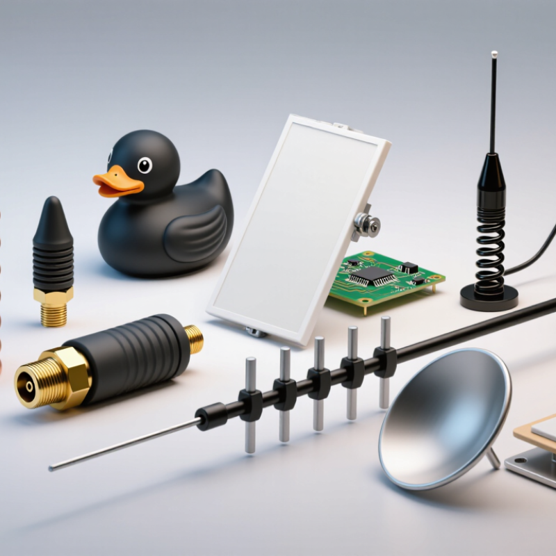
SMA Antennas: Connector Basics and Operating Principles
An SMA antenna connects to radio equipment through a compact, threaded coaxial interface. The threads hold the connection steady, while the center conductor carries the RF signal. SMA interfaces are commonly designed for 50-ohm systems, but connector fit alone does not guarantee good performance. Small parts matter.
SMA connector names can be confusing because shell shape and center contacts both affect compatibility. Check whether each side has a center pin or socket, and confirm the interface type before mating them. Standard and reverse-polarity versions may look similar but are not interchangeable. Tighten connections securely, using the equipment maker’s specified method; overtightening can damage delicate threads or internal contacts.
The antenna converts electrical energy into radio waves, and receives waves by producing a small voltage at its feed point. Its operating range depends on the antenna design, not merely the SMA connector. Cable length, nearby metal, and the radio’s matching network can also change measured results. A short antenna placed beside a metal panel may behave differently from the same unit on an open bench. I still find placement easy to underestimate. Not always obvious. Check the antenna’s stated frequency range, then verify the assembled setup with suitable test equipment when performance matters.
Top 10 SMA Antenna Types for Global Buyers — SMA Antennas: Connector Basics and Operating Principles
SMA describes a threaded coaxial connector interface, not an antenna design. The antenna types below can use an SMA feed when the connector, frequency range, impedance, and mechanical arrangement are appropriately matched.
| Antenna Type | Operating Principle | Typical Frequency Use | Common Polarization | Typical Applications | SMA Selection Notes |
|---|---|---|---|---|---|
| Quarter-Wave Monopole | A conductive element approximately one-quarter wavelength long operates against a ground plane, which acts as the antenna’s electrical image. | Design-dependent; common in sub-GHz and 2.4 GHz systems. | Usually linear; often vertical when mounted upright. | Compact radios, telemetry, wireless modules, and portable equipment. | Check the required ground-plane size and mounting orientation. A connector-mounted version commonly uses an SMA plug or jack at the device interface. |
| Half-Wave Dipole | Two conductive arms, each roughly one-quarter wavelength long, carry RF currents that produce a broadside radiation pattern. | Design-dependent; available for many VHF, UHF, and microwave bands. | Linear, determined by the orientation of the arms. | Test setups, access points, radio equipment, and general-purpose communications. | Confirm that the feed is designed for a 50-ohm system and that the antenna’s connector gender matches the equipment. |
| Whip Antenna | A straight, usually flexible or semi-rigid conductor radiates as a monopole or related resonant element. | Band-specific; commonly selected for VHF, UHF, or 2.4 GHz equipment. | Usually linear. | Portable radios, gateways, sensors, and wireless test devices. | Compare the specified operating band, whip length, and mounting clearance. A physically similar whip may not be resonant at the desired frequency. |
| Rubber-Duck Antenna | A short helical conductor is commonly loaded inside a flexible protective covering to reduce physical length. | Band-specific; often used in VHF and UHF products. | Usually linear, depending on installation. | Handheld radios and compact portable devices where a flexible antenna is useful. | Electrical loading can reduce efficiency compared with a full-size resonant antenna. Verify the exact band and connector orientation. |
| Stubby Antenna | A shortened, electrically loaded element trades physical size for bandwidth or radiation efficiency, depending on its design. | Band-specific; typically designed for a defined radio band. | Usually linear. | Compact terminals, handheld equipment, and installations with limited clearance. | Check measured or specified performance in the installed position; nearby enclosures and the user’s hand can affect tuning. |
| Helical Antenna | A wire or conductor wound into a helix radiates according to its dimensions and operating mode; compact versions may behave as loaded monopoles. | Design-dependent; used from VHF and UHF through microwave frequencies. | Linear or circular, depending on helix geometry and operating mode. | Compact communication devices, satellite links, and specialized radio systems. | Do not infer polarization from appearance alone. Confirm the specified polarization, frequency range, and required ground plane. |
| PCB Trace Antenna | A patterned copper trace on a circuit board forms a resonant radiator, often using a monopole, inverted-F, or related layout. | Commonly designed for bands such as 2.4 GHz; other bands require different layouts. | Usually linear; depends on board layout and orientation. | Embedded wireless modules, compact electronics, and custom circuit boards. | An SMA connector may provide an external feed or test point. Board ground, clearance, enclosure materials, and feed layout affect tuning. |
| Microstrip Patch Antenna | A conductive patch above a ground plane resonates at a frequency set mainly by patch dimensions and substrate properties. | Design-dependent; commonly used at microwave frequencies, including GNSS and WLAN bands. | Linear or circular, depending on the patch and feed design. | Positioning receivers, embedded systems, and directional or low-profile wireless equipment. | Check whether the patch is designed for the intended ground plane and whether any required matching network or cable is included. |
| Yagi-Uda Antenna | A driven element works with parasitic reflector and director elements to concentrate radiation in a preferred direction. | Band-specific; commonly used in VHF and UHF applications. | Usually linear. | Point-to-point links, monitoring, and directional reception or transmission. | Assess gain, beamwidth, front-to-back behavior, and alignment requirements. SMA is typically a feed interface rather than a structural mounting method. |
| Log-Periodic Dipole Array | Multiple elements of progressively changing lengths provide broadband directional operation across a designed frequency range. | Broadband within the antenna’s specified design range; range varies substantially by model. | Usually linear. | Broadband testing, spectrum monitoring, and directional communications. | Confirm the full frequency range and input impedance across that range. Check cable and connector ratings at the highest intended frequency. |
Connector basics: standard SMA interfaces are threaded coaxial connectors commonly designed for nominal 50-ohm systems. Standard SMA and reverse-polarity SMA (RP-SMA) use different center-contact arrangements and are not interchangeable by appearance alone. Connector frequency limits depend on the specific interface, construction, and manufacturer specification. Antenna frequency ranges and performance also depend on the complete design and installation.

Contact us
Please fill out the enquiry form, and our dedicated team will promptly attend to your request