What Are the Top Transformer Core Types?
Choosing the right transformer core is not a cosmetic decision. It affects efficiency, temperature rise, noise, size, cost, and long-term reliability. The most suitable Transformer Core Types depend on frequency, power level, insulation requirements, waveform quality, and operating conditions.
Common choices include laminated E-I cores, C-cores, toroidal cores, ferrite cores, and advanced amorphous or nanocrystalline materials. Laminated steel cores remain practical for many 50 or 60 Hz power transformers. Ferrite cores usually perform better at high frequencies because they limit eddy-current losses. Toroidal designs can reduce leakage flux and audible hum, although winding and assembly may require more careful control. Each choice matters.
There is no universal winner.
A useful comparison should examine magnetic saturation, core loss, thermal behavior, mechanical strength, and manufacturing complexity. Real-world testing also matters. A design that looks efficient on paper may run hotter after winding tension, air gaps, or imperfect clamping are considered. The boundary is not always clean. For example, a compact ferrite core may suit a switching supply, while a larger laminated core may provide better durability in an industrial environment.
This overview evaluates the top Transformer Core Types through practical engineering criteria rather than simple popularity. It considers where each core works well, where it becomes less effective, and which compromises designers often overlook. Some rankings may change with the application. That is worth remembering. Reliable selection begins with measured requirements, verified material data, and careful attention to operating temperature and frequency.
What a Transformer Core Is and How It Shapes Performance
What Are the Top Transformer Core Types?
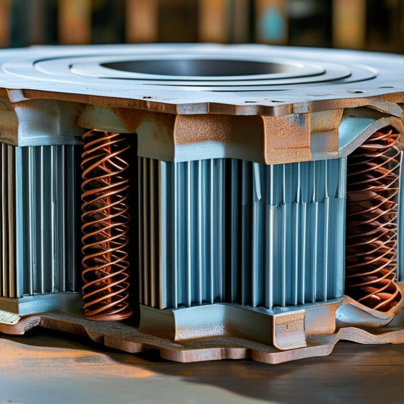
A transformer core guides magnetic flux between windings. Its material and shape directly influence efficiency, heat, noise, and size. Laminated silicon-steel cores suit common power-frequency transformers. Thin layers reduce eddy-current losses. Ferrite cores perform better at high frequencies, where steel can waste energy through heat. Toroidal cores use a continuous ring, reducing leakage flux and audible vibration. However, they can be harder to wind and assemble.
Core selection also depends on saturation. A saturated core draws excessive current and may overheat quickly. During practical testing, I have seen a small ferrite core remain cool at high frequency but fail badly at low frequency. That mistake taught me to match the core to the operating range, not just its physical size. Powdered-iron cores can handle useful energy storage in certain inductive designs. Amorphous materials may reduce losses, although cost and availability can affect the decision. No core type wins everywhere.
Tips: Check frequency, power, temperature, and expected flux density together. Leave a sensible safety margin. Measure winding temperature after continuous operation. A quiet transformer is not always an efficient one. Inspect waveforms, too. Distortion can reveal hidden saturation. When uncertain, compare calculated losses with real test data. Small design assumptions often create large thermal problems.
What Are the Top Transformer Core Types? — What a Transformer Core Is and How It Shapes Performance
| Transformer Core Type | Typical Core Material | Common Operating Frequency | Typical Power Range | Relative Magnetic Permeability | Core Loss Characteristics | Main Performance Strength | Typical Applications | Key Advantages | Main Limitations |
|---|---|---|---|---|---|---|---|---|---|
| Laminated Silicon Steel Core | Grain-oriented or non-oriented electrical steel laminations, commonly insulated and stacked to reduce eddy currents. | Approximately 25–400 Hz; most commonly used at 50 or 60 Hz. | From small control transformers to utility-scale power transformers. | High, typically in the thousands under suitable magnetic-field conditions. | Low loss at power frequency when the laminations are thin and properly oriented; loss increases with frequency and excessive flux density. | Excellent efficiency for mains-frequency power conversion. | Distribution transformers, power transformers, industrial control transformers, and low-frequency isolation transformers. | High saturation flux density, mature manufacturing methods, strong mechanical robustness, and good cost-to-performance balance. | Heavy and relatively bulky; unsuitable for efficient operation at high switching frequencies because eddy-current and hysteresis losses rise. |
| Ferrite Core | Soft manganese-zinc or nickel-zinc ceramic ferrite. | Approximately 10 kHz to several hundred kilohertz; the practical range depends on material grade and temperature. | Typically from a few watts to several kilowatts in high-frequency designs. | Moderate to high, commonly from several hundred to several thousand depending on composition and frequency. | Very low electrical conductivity greatly reduces eddy-current loss at high frequency; hysteresis loss and temperature effects remain important. | Strong high-frequency performance with low eddy-current loss. | Switch-mode power supplies, high-frequency transformers, gate-drive transformers, compact adapters, and electromagnetic interference filters. | High electrical resistivity, low high-frequency loss, low weight, and availability in many compact shapes. | Lower saturation flux density than steel; brittle ceramic construction and reduced performance under high direct-current bias. |
| Amorphous Metal Core | Rapidly solidified iron-based metallic glass with a disordered atomic structure. | Usually 50 or 60 Hz, with some specialized higher-frequency applications. | Most common in medium- to high-power energy-efficient transformers. | High, with magnetic behavior dependent on alloy, heat treatment, and operating conditions. | Very low no-load loss compared with conventional electrical steel, especially at typical distribution-transformer flux densities. | Outstanding energy efficiency during continuous energized operation. | Energy-efficient distribution transformers and applications where no-load losses are a major operating cost. | Reduced core loss, lower lifetime energy consumption, and good performance at power frequency. | More difficult processing, higher material and manufacturing complexity, lower mechanical stiffness, and potentially higher audible noise or manufacturing sensitivity. |
| Nanocrystalline Core | Ultrafine-grain iron-based alloy produced by controlled crystallization of an amorphous precursor. | Approximately 1 kHz to several hundred kilohertz, depending on geometry, material, and flux level. | From tens of watts to several kilowatts; larger assemblies are possible for specialized equipment. | Very high effective permeability, often higher than conventional ferrite in suitable frequency ranges. | Very low core loss over a broad high-frequency range, with good behavior in common-mode and power magnetic applications. | High permeability combined with low loss and high saturation capability. | High-frequency power transformers, common-mode chokes, current transformers, renewable-energy converters, and high-performance power supplies. | Compact magnetic components, high impedance per turn, good frequency response, and better saturation capability than many ferrites. | Higher material cost, specialized processing, sensitivity to mechanical stress, and limited availability in some shapes and sizes. |
| Powdered Iron Core | Iron powder particles insulated from one another and compressed with a distributed air gap. | Approximately 10 kHz to 100 kHz, with the usable range depending strongly on material and flux level. | Typically low- to medium-power magnetic components. | Moderate effective permeability because the distributed air gap lowers the overall permeability. | Higher loss than ferrite or nanocrystalline materials at many high frequencies, but the distributed gap can provide predictable energy storage. | Good distributed-gap behavior for energy storage and resistance to saturation. | Power inductors, energy-storage inductors, DC chokes, and selected high-frequency transformers. | Distributed air gap, good DC-bias tolerance, mechanical versatility, and useful energy-storage capability. | Higher core loss, lower permeability, and greater temperature dependence than many alternative high-frequency materials. |
| Air Core | No magnetic material; the magnetic circuit is formed through air or another nonmagnetic medium. | From audio and radio frequencies to very high frequencies. | Generally low power, although specialized air-core transformers can handle higher power with suitable cooling and geometry. | Approximately 1, because air has very low relative permeability. | No magnetic-core hysteresis or core eddy-current loss; winding loss and leakage-field loss can be significant. | No core saturation and excellent suitability for very high-frequency operation. | Radio-frequency coupling, resonant circuits, wireless charging structures, measurement equipment, and specialized isolation designs. | No core loss, no saturation, broad frequency capability, and highly linear magnetic behavior. | Low inductance per turn, weak magnetic coupling unless the windings are carefully arranged, larger winding size, and greater electromagnetic leakage. |
| C-Core | Usually laminated electrical steel, amorphous metal, or another strip-wound magnetic material formed into two C-shaped sections. | Commonly 50 or 60 Hz; high-frequency versions may use suitable ferrite or metallic materials. | Small, medium, and high-power transformers depending on core material and construction. | High, determined by the selected magnetic material and any intentional air gap. | Comparable to the selected core material; carefully finished mating surfaces can reduce magnetic reluctance and associated excitation current. | Efficient magnetic path with convenient winding assembly and serviceability. | Power transformers, audio transformers, industrial transformers, and custom magnetic components. | Low leakage potential, efficient assembly, reduced winding handling, and flexible mechanical construction. | Requires accurate mating of the core halves; joints can add reluctance, vibration, and manufacturing complexity. |
| Toroidal Core | Ferrite, laminated steel, powdered iron, amorphous metal, or nanocrystalline material wound or formed into a ring. | From power frequency to high frequency, depending on the core material. | From small signal levels to several kilovolt-amperes and beyond in specialized designs. | High when a high-permeability magnetic material is used; effective permeability depends on material and geometry. | Usually low leakage flux and efficient magnetic utilization; actual loss follows the selected core material and frequency. | High magnetic efficiency with low external leakage field. | Audio transformers, power supplies, isolation transformers, current transformers, and compact mains transformers. | Low magnetizing current, compact size, low electromagnetic radiation, and good winding utilization. | Winding can be labor-intensive, insulation placement may be difficult, and thermal management can be less convenient. |
| E-I Laminated Core | Interleaved E-shaped and I-shaped electrical-steel laminations. | Most commonly 50 or 60 Hz; some specialized versions operate at lower audio frequencies. | From small control transformers to medium-power transformers. | High, with effective permeability influenced by the joint structure and any air gap. | Low at power frequency when suitable steel and lamination thickness are used; joints can increase magnetizing current and audible vibration. | Simple, economical, and versatile construction. | Control transformers, audio transformers, small power transformers, and general-purpose isolation transformers. | Easy winding access, scalable dimensions, straightforward manufacturing, and convenient mounting. | Higher leakage flux and mechanical noise than many toroidal designs; joints may reduce magnetic efficiency. |

Contact us
Please fill out the enquiry form, and our dedicated team will promptly attend to your request